
What Is Fibridge Switch Backplane Bandwidth
The backplane bandwidth of a switch is the maximum amount of data that can be throughput between the switch interface processors or interface cards and the data bus. The backplane bandwidth signifies the overall data switching capacity of the switch, with units in Gbps. It is also known as switching bandwidth. Typically, the backplane bandwidth of a switch ranges from a few Gbps to several thousand Gbps. The higher the backplane bandwidth of a switch, the greater its ability to handle data, but the design costs also increase accordingly.
What is Backplane in Networking
Backplane of switch a PCB board located on the back inner side of the frame, which serves as the backplane for the frame switch. It is used to connect the engine, switching matrix, line card, fan, and power supply of the frame switch. It is similar to the motherboard of a computer (graphics cards and sound cards are inserted into the motherboard), providing various channels for power supply, data, management, and control planes for the plug-in cards.
What is Switching Capacity
The backplane bandwidth of a switch is the maximum amount of data that can be transmitted between the interface processor or interface card and the data bus of the switch. Backplane bandwidth represents data exchange capacity of the switch, measured in Gbps, also known as switching bandwidth. The backplane bandwidth of a switch typically ranges from several Gbps to several hundred Gbps. The higher the backplane bandwidth of a switch, the stronger its ability to handle data, but the higher the design cost will also be.
Line-Rate Backplane Bandwidth
Consider the total bandwidth that all ports on the switch can provide. The calculation formula is number of ports * corresponding port speed * 2 (full-duplex mode). If the total bandwidth calculated by this formula is ≤ the nominal backplane bandwidth of the specific switch, then the switch is line-rate in terms of backplane bandwidth; otherwise, it cannot achieve full line-rate switching.
Layer 2 Packet Forwarding Rate
Layer 2 packet forwarding rate = number of 10Gb ports × 14.88Mpps + number of gigabit ports × 1.488Mpps + number of hundred-megabit ports * 0.1488Mpps + number of other types of ports * corresponding calculation method. If this rate is ≤ the nominal layer 2 packet forwarding rate in the switch's datasheet, then the switch can achieve full line-rate switching when performing layer 2 switching.
Layer 3 Packet Forwarding Line Rate
Layer 3 packet forwarding rate = number of 10Gb ports × 14.88Mpps + number of gigabit ports × 1.488Mpps + number of hundred-megabit ports * 0.1488Mpps + number of other types of ports * corresponding calculation method. If this rate is ≤ the nominal layer 3 packet forwarding rate in the switch's datasheet, then the switch can achieve full line-rate switching at the port level when performing layer 3 switching.
The standard for measuring the line-rate packet forwarding rate is based on the number of 64-byte (minimum packet size) data packets sent per unit time. For gigabit oem ethernet switch, the calculation method is as follows: 1,000,000,000bps / 8bit / (64+8+12)byte = 1,488,095pps. Note: For 64-byte Ethernet frames, the fixed overhead of 8-byte frame headers and 12-byte inter-frame gaps must be considered. Therefore, the packet forwarding rate for a line-rate gigabit Ethernet port when forwarding 64-byte packets is 1.488Mpps. Fast Ethernet lines' port packet forwarding rate is exactly one-tenth of that of gigabit Ethernet, i.e., 148.8 kpps.
For 10Gb Ethernet, the packet forwarding rate for a line-rate port is 14.88Mpps.
For gigabit Ethernet, the packet forwarding rate for a line-rate port is 1.488Mpps.
For hundred-megabit fast Ethernet, the packet forwarding rate for a line-rate port is 0.1488Mpps.
For OC-12 POS ports, the packet forwarding rate for a line-rate port is 1.17Mpps.
For OC-48 POS ports, the packet forwarding rate for a line-rate port is 468 MppS.
The utilization rate of backplane bandwidth resources is closely related to the internal structure of the switch such as core switch and access switch.
The Main Internal Structures of Switches Are as Follows:
One is the shared memory structure, which relies on a central switching engine to provide high-performance connections for all ports by having the core engine inspect each incoming packet to determine its routing. This method requires large memory bandwidth and high management costs, especially as the number of switch ports increases, the price of central memory becomes very high, and hence the switch core becomes a performance bottleneck.
The second is the crossbar bus structure, which can establish direct point-to-point connections between ports, excellent for single-point transmission performance, but unsuitable for multi-point transmission.
The third is the hybrid crossbar bus structure, which is a mixed crossbar bus implementation that divides the unified crossbar matrix into smaller crossbar matrices connected by a high-performance bus. Its advantages are reduced number of crossbar buses, lower costs, and reduced bus contention; however, the bus connecting the crossbar matrices becomes a new performance bottleneck.

Take the Fibridge's managed network switch with 2 Giga SFP and 24 gigabit Ethernet ports as an example. For the device to achieve full line-rate switching, the backplane bandwidth should not be less than (24+2) x2 = 52Gbps, and the packet forwarding rate should not be less than (24+2) x1.488MPPS = 38.688Mpps. According to the parameters provided by Fibridge, this switch fully meets the requirements for full line-rate switching.
Theoretically, the higher the performance indicators of a switch, the better, but for a standalone network switch, having a backplane bandwidth higher than full line-rate is meaningless.
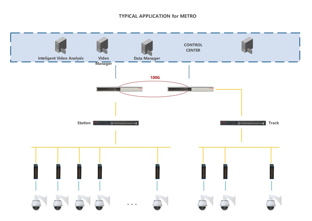
Take IP network video surveillance, where network switches are widely used, as an example. In the foundational network architecture, the front-end access switches typically connect directly to IP cameras.
In the most commonly used 2-megapixel HD image 1080x1920P monitoring system, the actual bitstream bandwidth of a 2-megapixel HD network camera, which uses Mpeg-4 compression encoding, is usually not higher than 10M. Therefore, even considering margin, the port speed is far below 1G, reducing actual backplane bandwidth requirements significantly. For a front-end network switch with 2 gig SFP ports and 24 gigabit Ethernet ports, must the device achieve full line-rate switching and use a switch with backplane bandwidth above 52Gbps and a packet forwarding rate of 36.688MPPS? Given that each port's actual bandwidth after Mpeg4 compression is typically not higher than 10M and the packet forwarding rate is only 0.01488Mbps, even with margin, the port rate is far below 1.488Mbps, significantly reducing the need for high backplane bandwidth and packet forwarding rates. Based on these data, in actual system design, we can choose switches with appropriate performance that offer better cost-performance ratio and higher stability.
Though network switch oem at the access point that don't achieve full line-rate has practical engineering uses. But in systems exceeding the switch port numbers at access points, the full line-rate metric becomes very valuable and should be given high priority. Still, take Fibridge's managed full-gigabit switch with 2 SFP ports and 24 Ethernet ports as an example. Since this switch achieves full line-rate switching, based on prior analysis, it can serve as the equivalent of a 2 SFP 48 Ethernet or even 2 SFP 72 Ethernet switch through simple cascading, fully connecting 48 to 72 2-megapixel 1080x1920P HD cameras. From this basic principle, for larger systems with more surveillance points, using Fibridge's higher-performing managed 4 10Gb SFP and 24 gigabit switch in a cascaded setup can flexibly design the network topology of a medium-to-large HD network image surveillance system, making it simple and easy.
In the design of network equipment within a system, various integrated factors need to be considered. However, front-end access switches usually have the most ports, so we should appropriately select based on actual usage. While excessively high backplane bandwidth is meaningless, undoubtedly, in network architecture design, we must fully consider the full line-rate indicator. After all, saving costs while increasing the stability of the entire system is highly meaningful.


 English
 中文
中文 русский
 Español
 français